Cd5220 Pole Display Drivers
• User’s Manual Models CD5220 / CD6220 Vacuum Fluorescent Customer Display.  • INDEX FEATURES. 3 TYPE CLASSIFICATION. 4 GENERAL SPECIFICATIONS. 5 INTERFACE SPECIFICATIONS. 6 FUNCTION SELECTION. 10 CHARACTER SET.
Partner Tech Customer Pole Displays - CD-7220, CD-8220, CD5220. The CD-6220 is a 2x20, 11mm large character size customer pole display with a vacuum fluorescent display (VFD) tube presenting bright and large easy to read characters. Idm crack torrent file. Click for details. The CD-5220 is a 2x20 character customer pole display that has two pole sections giving you the choice of four different display heights. Click for details. Please make sure following parts are found in the customer display box. 3.1 VFD Pole Display for 720/750 Monitor VFD Pole Display For 720/750 Monitor Figure:720 with 300dx PC and Pole Display The parts of the Pole Display kits: (Part no. P07304) (1)Pole Display Module (2)Flat Cable (RJ-45 to DB-9F flat cable connector ).
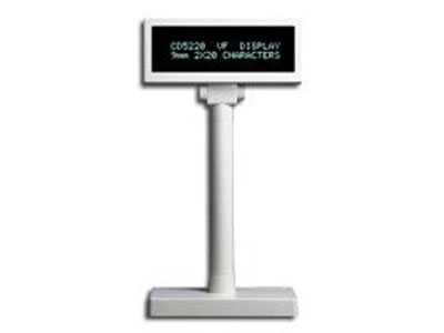
16 INSTALLATION GUIDE. 21 CD5220 customer display. • CD5220 customer display 1. FEATURES 40 Characters (20 columns x 2 lines).
Easy to read blue-green fluorescent color and large characters. Adjustable viewing angle of 8-35 and rotation angle of 270. Two segment poles provide 4 adjustable heights. DIP switch selectable emulation modes: CD5220 AEDEX ADM787. TYPE CLASSIFICATION CD5220 No Type name I Mode No.
II Interface III Base section IV Power input V Power adapter IV Pass through function CD5220 customer display Type name Description CD5220 CD5220 display CD6220 CD6220 display Serial port (RS232C) Parallel port (Centronics) Rectangle base Circular base. GENERAL SPECIFICATIONS ITEM 1 Display method 2 Number of character 3 Display color 4 Luminance 5 Character type 6 Character font 7 Character size 8 Character pitch 9 Power supply 10 Power consumption 11 MTBF-power on time Dimensions (mm) 13 Viewing angle 14 Rotation angle 15 Weight. INTERFACE SPECIFICATIONS 4.1. Communication 4.1.1.
Serial port (RS232C) communication (a) The interface specification are based on EIA RS232C baud rate 9600 or 4800 bps ( selectable by DIP switch, refer Table 4-7) 8 data bits, no parity, 1 or more stop bits (RS232C) ERIAL PORT COMMUNICATION FLOW. RS232C interface to printer cable Printer side connector pin assignment Connector type: D-sub 25 pin (Male) Signal direction RXD From printer to PC/Host Printer status data TXD From display to printer From printer to display From PC/Host to printer PC/Host ready signal DTR From PC/Host to printer PC/Host ready signal DSR From printer to display CD5220 customer display. • 4.2 Serial port interface for rectangle basic section A. Serial port interface connector position for rectangle basic section FRAME GND 5V or 12v RS232C to printer connector RS232C to PC/host connector Power input connector B. Power input Connector type: DC JACK (5.5/2.1) C.
FUNCTION SELECTION 5.1 Baud rate SW number SW1 Notes: SW1 is ignored when the baud rate is stored to the EEPROM. Baud rate will be referred to the EEPROM baud rate status. 5.2 International character set SW number SW2 SW3 SW4 SW5 International character OFF OFF OFF OFF U.S.A. COMMAND 6.1 PTC standard mode command list Command Code description(hex) Function description ESC DC1 1B 11 ESC DC2 1B 12 ESC DC3 1B 13 ESC Q A.CR 1B 51 41 [n ]x20 0D ESC Q B.CR 1B 51 42 [n ]x20 0D ESC Q D.CR 1B 51 44 [n ]xm 0D m.